Renewing the Nikko Turbo 2 RC Car
Vintage 1980s Nikko remote control RC car mascot.
Components and supplies
5 mm LED: Red
Arduino Nano R3
5 mm LED: Green
HC-06 Bluetooth Module
Dual H-Bridge motor drivers L298
Buzzer, Piezo
Resistor 221 ohm
Tools and machines
Soldering iron (generic)
Solder Flux, Soldering
Hot glue gun (generic)
Drill / Driver, Cordless
Apps and platforms
Arduino IDE
Project description
Code
Arduino code for the NIKKO Turbo II RC Car
arduino
Engine 2 is the Magnetic steering system used in NIKKO. If another type is needed, the necessary changes must be made.
1//including the libraries
2#include <SoftwareSerial.h> // TX RX software   library for bluetooth
3
4//Defining pins for RGB led
5#define GREEN 12
6#define   RED 11
7#define delayTime 3
8
9//Initializing pins for bluetooth Module
10int   bluetoothTx = 8; // bluetooth tx to 2 pin
11int bluetoothRx = 7; // bluetooth rx   to 3 pin
12SoftwareSerial bluetooth(bluetoothTx, bluetoothRx);
13//Front Motor   Pins
14int Enable1 = 3;
15int Motor1_Pin1 = 2;
16int Motor1_Pin2 = 4;
17//Back   Motor Pins
18int Motor2_Pin1 = 5;
19int Motor2_Pin2 = 9;
20int Enable2   = 10;
21//Front Light pins
22int front_light1 = GREEN;
23//Back light pins
24int   back_light1 = RED;
25int horn = 6;
26char command ; //variable to store the data
27int   velocity = 0; //Variable to control the speed of motor
28void setup()
29{
30   //Set the baud rate of serial communication and bluetooth module at same rate.
31   Serial.begin(9600);
32  bluetooth.begin(9600);
33  //Setting the L298N, LED   and RGB LED pins as output pins.
34  pinMode(Motor1_Pin1, OUTPUT);
35  pinMode(Motor1_Pin2,   OUTPUT);
36  pinMode(Enable1, OUTPUT);
37  pinMode(Motor2_Pin1, OUTPUT);
38   pinMode(Motor2_Pin2, OUTPUT);
39  pinMode(Enable2, OUTPUT);
40  pinMode(front_light1,   OUTPUT);
41  pinMode(back_light1, OUTPUT);
42  pinMode(horn, OUTPUT);
43  pinMode(GREEN,   OUTPUT);
44  pinMode(RED, OUTPUT);
45  //Setting the enable and LED pins as HIGH.
46   digitalWrite(GREEN, HIGH);
47  digitalWrite(RED, HIGH);
48  digitalWrite(Enable2,   HIGH);
49  digitalWrite(back_light1, LOW);
50  digitalWrite(front_light1, LOW);
51}
52void   loop(){
53  if(bluetooth.available() > 0){  //Checking if there is some data available   or not
54    command = bluetooth.read();   //Storing the data in the 'command'   variable
55    Serial.println(command);      //Printing it on the serial monitor
56
57    //Change pin mode only if new command is different from previous.
58     switch(command){
59    case 'F':  //Moving the Car Forward
60      digitalWrite(Motor1_Pin1,   LOW);
61      digitalWrite(Motor1_Pin2, HIGH);
62      digitalWrite(Motor2_Pin1,   LOW);
63      digitalWrite(Motor2_Pin2, LOW);
64      break;
65    case 'L':   //Moving the Car Forward Left90
66      digitalWrite(Motor1_Pin1, LOW);
67      digitalWrite(Motor1_Pin2,   HIGH);
68      digitalWrite(Motor2_Pin1, LOW);
69      digitalWrite(Motor2_Pin2,   HIGH);
70      delay (30);
71      digitalWrite(Motor2_Pin1, LOW);
72      digitalWrite(Motor2_Pin2,   LOW);
73      break;
74    case 'G':  //Moving the Car Forward Left45
75      digitalWrite(Motor1_Pin1,   LOW);
76      digitalWrite(Motor1_Pin2, HIGH);
77      digitalWrite(Motor2_Pin1,   LOW);
78      digitalWrite(Motor2_Pin2, HIGH);
79      delay (30);
80      digitalWrite(Motor2_Pin1,   LOW);
81      digitalWrite(Motor2_Pin2, LOW);
82      break;
83    case 'R':    //Moving the Car Forward Right90
84      digitalWrite(Motor1_Pin1, LOW);
85       digitalWrite(Motor1_Pin2, HIGH);
86      digitalWrite(Motor2_Pin1, HIGH);
87       digitalWrite(Motor2_Pin2, LOW);
88      delay (30);
89      digitalWrite(Motor2_Pin1,   LOW);
90      digitalWrite(Motor2_Pin2, LOW);
91      break;
92    case 'I':   //Moving the Car Forward Right45
93      digitalWrite(Motor1_Pin1, LOW);
94       digitalWrite(Motor1_Pin2, HIGH);
95      digitalWrite(Motor2_Pin1, HIGH);
96       digitalWrite(Motor2_Pin2, LOW);
97      delay (30);
98      digitalWrite(Motor2_Pin1,   LOW);
99      digitalWrite(Motor2_Pin2, LOW);
100      break;
101    case 'S':    //Stop
102      digitalWrite(Motor1_Pin2, LOW);
103      digitalWrite(Motor1_Pin1,   LOW);
104      digitalWrite(Motor2_Pin2, LOW);
105      digitalWrite(Motor2_Pin1,   LOW);
106      break;
107    case 'B':  //Moving the Car Backward
108      digitalWrite(Motor1_Pin1,   HIGH);
109      digitalWrite(Motor1_Pin2, LOW);
110      break;
111    case 'J':   //Moving the Car backward Right90
112      digitalWrite(Motor1_Pin2, LOW);
113       digitalWrite(Motor1_Pin1, HIGH);
114      digitalWrite(Motor2_Pin1, HIGH);
115       digitalWrite(Motor2_Pin2, LOW);
116      delay (30);
117      digitalWrite(Motor2_Pin1,   LOW);
118      digitalWrite(Motor2_Pin2, LOW);
119      break;
120   case   'H':  //Moving the Car backward Left90
121      digitalWrite(Motor1_Pin1, HIGH);
122       digitalWrite(Motor1_Pin2, LOW);
123      digitalWrite(Motor2_Pin1, LOW);
124       digitalWrite(Motor2_Pin2, HIGH);
125      delay (30);
126      digitalWrite(Motor2_Pin1,   LOW);
127      digitalWrite(Motor2_Pin2, LOW);
128      break;
129    case 'W':   //Front light ON
130      digitalWrite(front_light1, HIGH);
131      break;
132     case 'w':  //Front light OFF
133      digitalWrite(front_light1, LOW);
134      break;
135     case 'U':  //Back light ON
136      digitalWrite(back_light1, HIGH);
137      break;
138     case 'u':  //Back light OFF
139      digitalWrite(back_light1, LOW);
140      break;
141    case 'V':  //Horn On
142{
143  int i = 200; // The starting pitch
144  while(i   < 800) {
145    i++;
146    tone(horn, i); // Emit the noise
147    delay(5);
148   }
149  delay(100); // A short break in between each whoop
150}
151      break;
152    case 'v':  //Horn OFF
153       noTone(horn);
154      break;
155    case   'x': //Turn ON Everything
156    break;
157    case 'X': //Turn OFF Everything
158       break;
159
160    //Controlling the Speed of Car
161default:  //Get velocity
162       if(command=='q'){
163        velocity = 255;  //Full velocity
164        analogWrite(Enable1,   velocity);
165      }
166      else{
167        //Chars '0' - '9' have an integer   equivalence of 48 - 57, accordingly.
168        if((command >= 48) && (command <=   57)){
169          //Subtracting 48 changes the range from 48-57 to 0-9.
170          //Multiplying   by 25 changes the range from 0-9 to 0-225.
171          velocity = (command - 48)*25;
172          analogWrite(Enable1, velocity);
173        }
174      }
175       }
176  }
177}
178
Arduino code for the NIKKO Turbo II RC Car
arduino
Engine 2 is the Magnetic steering system used in NIKKO. If another type is needed, the necessary changes must be made.
1//including the libraries
2#include <SoftwareSerial.h> // TX RX software  library for bluetooth
3
4//Defining pins for RGB led
5#define GREEN 12
6#define  RED 11
7#define delayTime 3
8
9//Initializing pins for bluetooth Module
10int  bluetoothTx = 8; // bluetooth tx to 2 pin
11int bluetoothRx = 7; // bluetooth rx  to 3 pin
12SoftwareSerial bluetooth(bluetoothTx, bluetoothRx);
13//Front Motor  Pins
14int Enable1 = 3;
15int Motor1_Pin1 = 2;
16int Motor1_Pin2 = 4;
17//Back  Motor Pins
18int Motor2_Pin1 = 5;
19int Motor2_Pin2 = 9;
20int Enable2  = 10;
21//Front Light pins
22int front_light1 = GREEN;
23//Back light pins
24int  back_light1 = RED;
25int horn = 6;
26char command ; //variable to store the data
27int  velocity = 0; //Variable to control the speed of motor
28void setup()
29{
30  //Set the baud rate of serial communication and bluetooth module at same rate.
31  Serial.begin(9600);
32  bluetooth.begin(9600);
33  //Setting the L298N, LED  and RGB LED pins as output pins.
34  pinMode(Motor1_Pin1, OUTPUT);
35  pinMode(Motor1_Pin2,  OUTPUT);
36  pinMode(Enable1, OUTPUT);
37  pinMode(Motor2_Pin1, OUTPUT);
38  pinMode(Motor2_Pin2, OUTPUT);
39  pinMode(Enable2, OUTPUT);
40  pinMode(front_light1,  OUTPUT);
41  pinMode(back_light1, OUTPUT);
42  pinMode(horn, OUTPUT);
43  pinMode(GREEN,  OUTPUT);
44  pinMode(RED, OUTPUT);
45  //Setting the enable and LED pins as HIGH.
46  digitalWrite(GREEN, HIGH);
47  digitalWrite(RED, HIGH);
48  digitalWrite(Enable2,  HIGH);
49  digitalWrite(back_light1, LOW);
50  digitalWrite(front_light1, LOW);
51}
52void  loop(){
53  if(bluetooth.available() > 0){  //Checking if there is some data available  or not
54    command = bluetooth.read();   //Storing the data in the 'command'  variable
55    Serial.println(command);      //Printing it on the serial monitor
56
57    //Change pin mode only if new command is different from previous.
58    switch(command){
59    case 'F':  //Moving the Car Forward
60      digitalWrite(Motor1_Pin1,  LOW);
61      digitalWrite(Motor1_Pin2, HIGH);
62      digitalWrite(Motor2_Pin1,  LOW);
63      digitalWrite(Motor2_Pin2, LOW);
64      break;
65    case 'L':  //Moving the Car Forward Left90
66      digitalWrite(Motor1_Pin1, LOW);
67      digitalWrite(Motor1_Pin2,  HIGH);
68      digitalWrite(Motor2_Pin1, LOW);
69      digitalWrite(Motor2_Pin2,  HIGH);
70      delay (30);
71      digitalWrite(Motor2_Pin1, LOW);
72      digitalWrite(Motor2_Pin2,  LOW);
73      break;
74    case 'G':  //Moving the Car Forward Left45
75      digitalWrite(Motor1_Pin1,  LOW);
76      digitalWrite(Motor1_Pin2, HIGH);
77      digitalWrite(Motor2_Pin1,  LOW);
78      digitalWrite(Motor2_Pin2, HIGH);
79      delay (30);
80      digitalWrite(Motor2_Pin1,  LOW);
81      digitalWrite(Motor2_Pin2, LOW);
82      break;
83    case 'R':   //Moving the Car Forward Right90
84      digitalWrite(Motor1_Pin1, LOW);
85      digitalWrite(Motor1_Pin2, HIGH);
86      digitalWrite(Motor2_Pin1, HIGH);
87      digitalWrite(Motor2_Pin2, LOW);
88      delay (30);
89      digitalWrite(Motor2_Pin1,  LOW);
90      digitalWrite(Motor2_Pin2, LOW);
91      break;
92    case 'I':  //Moving the Car Forward Right45
93      digitalWrite(Motor1_Pin1, LOW);
94      digitalWrite(Motor1_Pin2, HIGH);
95      digitalWrite(Motor2_Pin1, HIGH);
96      digitalWrite(Motor2_Pin2, LOW);
97      delay (30);
98      digitalWrite(Motor2_Pin1,  LOW);
99      digitalWrite(Motor2_Pin2, LOW);
100      break;
101    case 'S':   //Stop
102      digitalWrite(Motor1_Pin2, LOW);
103      digitalWrite(Motor1_Pin1,  LOW);
104      digitalWrite(Motor2_Pin2, LOW);
105      digitalWrite(Motor2_Pin1,  LOW);
106      break;
107    case 'B':  //Moving the Car Backward
108      digitalWrite(Motor1_Pin1,  HIGH);
109      digitalWrite(Motor1_Pin2, LOW);
110      break;
111    case 'J':  //Moving the Car backward Right90
112      digitalWrite(Motor1_Pin2, LOW);
113      digitalWrite(Motor1_Pin1, HIGH);
114      digitalWrite(Motor2_Pin1, HIGH);
115      digitalWrite(Motor2_Pin2, LOW);
116      delay (30);
117      digitalWrite(Motor2_Pin1,  LOW);
118      digitalWrite(Motor2_Pin2, LOW);
119      break;
120   case  'H':  //Moving the Car backward Left90
121      digitalWrite(Motor1_Pin1, HIGH);
122      digitalWrite(Motor1_Pin2, LOW);
123      digitalWrite(Motor2_Pin1, LOW);
124      digitalWrite(Motor2_Pin2, HIGH);
125      delay (30);
126      digitalWrite(Motor2_Pin1,  LOW);
127      digitalWrite(Motor2_Pin2, LOW);
128      break;
129    case 'W':  //Front light ON
130      digitalWrite(front_light1, HIGH);
131      break;
132    case 'w':  //Front light OFF
133      digitalWrite(front_light1, LOW);
134      break;
135    case 'U':  //Back light ON
136      digitalWrite(back_light1, HIGH);
137      break;
138    case 'u':  //Back light OFF
139      digitalWrite(back_light1, LOW);
140      break;
141    case 'V':  //Horn On
142{
143  int i = 200; // The starting pitch
144  while(i  < 800) {
145    i++;
146    tone(horn, i); // Emit the noise
147    delay(5);
148  }
149  delay(100); // A short break in between each whoop
150}
151      break;
152    case 'v':  //Horn OFF
153       noTone(horn);
154      break;
155    case  'x': //Turn ON Everything
156    break;
157    case 'X': //Turn OFF Everything
158      break;
159
160    //Controlling the Speed of Car
161default:  //Get velocity
162      if(command=='q'){
163        velocity = 255;  //Full velocity
164        analogWrite(Enable1,  velocity);
165      }
166      else{
167        //Chars '0' - '9' have an integer  equivalence of 48 - 57, accordingly.
168        if((command >= 48) && (command <=  57)){
169          //Subtracting 48 changes the range from 48-57 to 0-9.
170          //Multiplying  by 25 changes the range from 0-9 to 0-225.
171          velocity = (command - 48)*25;
172          analogWrite(Enable1, velocity);
173        }
174      }
175      }
176  }
177}
178
Downloadable files
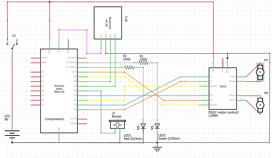
Wiring diagram for Nikko Turbo II RC Car
Engine 2 is the steering system, Battery are used by Nikko.
Wiring diagram for Nikko Turbo II RC Car
Documentation
Protoboard for Nikko Turbo II RC Car
The components are approximated from the actual ones used.
Protoboard for Nikko Turbo II RC Car
Protoboard for Nikko Turbo II RC Car
The components are approximated from the actual ones used.
Protoboard for Nikko Turbo II RC Car
Comments
Only logged in users can leave comments
MarcoGPS
0 Followers
•0 Projects
Table of contents
Intro
5
0