Components and supplies
6
3D Printable Parts
4
Rotary potentiometer (generic)
1
Arduino Nano R3
4
NeoPixel Ring: WS2812 5050 RGB LED
Tools and machines
1
3D Printer (generic)
1
Soldering iron (generic)
Project description
Code
Arduino Nano Code
arduino
1#include <Adafruit_GFX.h>
2#include <Adafruit_NeoMatrix.h>
3#include   <Adafruit_NeoPixel.h>
4
5#define NEO_PIN 6           // Neopixel pin
6#define   GND_PIN 9           // Signal pin used as ground
7#define GND_PIN2 1          //   Signal pin used as ground
8#define SPEED_PIN A4       // Analog (ADC) input pin   to read value of speed potentiometer
9#define COLOR_PIN A5       // Analog (ADC)   input pin to read value of color potentiometer
10#define MAX_BRIGHTNESS 50   //   Maximum Neopixel brightness
11#define UP_STEPS 5          // Increasing brightness   steps out of the total number of steps (smaller than half total => fast rise, slow   decay)
12#define TOTAL_STEPS 40      // Total number of increasing/deeasing steps
13#define   SPEED_DIVIDER 30    // Used to divide the value of the speed ADC readout to calculate   iteration delay
14
15const int heart[] = {       // Heart bitmap
16  0, 1, 1,   0, 1, 1, 0, 0,
17  1, 1, 1, 1, 1, 1, 1, 0,
18  1, 1, 1, 1, 1, 1, 1, 0,
19  1,   1, 1, 1, 1, 1, 1, 0,
20  0, 1, 1, 1, 1, 1, 0, 0,
21  0, 0, 1, 1, 1, 0, 0, 0,
22   0, 0, 0, 1, 0, 0, 0, 0,
23  0, 0, 0, 0, 0, 0, 0, 0
24};
25
26Adafruit_NeoMatrix   matrix = Adafruit_NeoMatrix(4, 4, 2, 2, NEO_PIN,
27  NEO_TILE_TOP   + NEO_TILE_LEFT    + NEO_TILE_COLUMNS   + NEO_TILE_ZIGZAG +
28  NEO_MATRIX_TOP + NEO_MATRIX_LEFT   + NEO_MATRIX_ROWS + NEO_MATRIX_ZIGZAG,
29  NEO_GRB + NEO_KHZ800);
30
31void setup()   {
32  matrix.begin();
33  matrix.setBrightness(40);
34
35  pinMode(GND_PIN,   OUTPUT);
36  digitalWrite(GND_PIN, LOW); // Lazy ground
37  pinMode(GND_PIN2,   OUTPUT);
38  digitalWrite(GND_PIN2, LOW); // Lazy ground
39  pinMode(SPEED_PIN,   INPUT);
40  pinMode(COLOR_PIN, INPUT);
41}
42
43void loop() {
44  int i, j;
45   int brightness;
46  int color;
47
48  for (i = 0; i < TOTAL_STEPS; i++) {
49     if (i < UP_STEPS)
50      brightness = MAX_BRIGHTNESS * i / UP_STEPS;
51    else
52       brightness = MAX_BRIGHTNESS * (TOTAL_STEPS - i - 1) / (TOTAL_STEPS - UP_STEPS);
53     matrix.setBrightness(brightness);
54    color = analogRead(COLOR_PIN) / 4;
55
56    for (j = 0; j < 64; j++) {
57
58      matrix.drawPixel(j / 8,   j % 8, Wheel(color)*heart[j]);
59
60    }
61
62
63    matrix.show();
64     delay(analogRead(SPEED_PIN) / SPEED_DIVIDER);
65  }
66}
67
68uint32_t Wheel(byte   WheelPos) { // Courtesy of multiple Adafruit examples
69  if (WheelPos < 85) {
70     return matrix.Color(WheelPos * 3, 255 - WheelPos * 3, 0);
71  } else if (WheelPos   < 170) {
72    WheelPos -= 85;
73    return matrix.Color(255 - WheelPos * 3, 0,   WheelPos * 3);
74  } else {
75    WheelPos -= 170;
76    return matrix.Color(0,   WheelPos * 3, 255 - WheelPos * 3);
77  }
78}
79
Arduino Nano Code
arduino
1#include <Adafruit_GFX.h>
2#include <Adafruit_NeoMatrix.h>
3#include  <Adafruit_NeoPixel.h>
4
5#define NEO_PIN 6           // Neopixel pin
6#define  GND_PIN 9           // Signal pin used as ground
7#define GND_PIN2 1          //  Signal pin used as ground
8#define SPEED_PIN A4       // Analog (ADC) input pin  to read value of speed potentiometer
9#define COLOR_PIN A5       // Analog (ADC)  input pin to read value of color potentiometer
10#define MAX_BRIGHTNESS 50   //  Maximum Neopixel brightness
11#define UP_STEPS 5          // Increasing brightness  steps out of the total number of steps (smaller than half total => fast rise, slow  decay)
12#define TOTAL_STEPS 40      // Total number of increasing/deeasing steps
13#define  SPEED_DIVIDER 30    // Used to divide the value of the speed ADC readout to calculate  iteration delay
14
15const int heart[] = {       // Heart bitmap
16  0, 1, 1,  0, 1, 1, 0, 0,
17  1, 1, 1, 1, 1, 1, 1, 0,
18  1, 1, 1, 1, 1, 1, 1, 0,
19  1,  1, 1, 1, 1, 1, 1, 0,
20  0, 1, 1, 1, 1, 1, 0, 0,
21  0, 0, 1, 1, 1, 0, 0, 0,
22  0, 0, 0, 1, 0, 0, 0, 0,
23  0, 0, 0, 0, 0, 0, 0, 0
24};
25
26Adafruit_NeoMatrix  matrix = Adafruit_NeoMatrix(4, 4, 2, 2, NEO_PIN,
27  NEO_TILE_TOP   + NEO_TILE_LEFT   + NEO_TILE_COLUMNS   + NEO_TILE_ZIGZAG +
28  NEO_MATRIX_TOP + NEO_MATRIX_LEFT  + NEO_MATRIX_ROWS + NEO_MATRIX_ZIGZAG,
29  NEO_GRB + NEO_KHZ800);
30
31void setup()  {
32  matrix.begin();
33  matrix.setBrightness(40);
34
35  pinMode(GND_PIN,  OUTPUT);
36  digitalWrite(GND_PIN, LOW); // Lazy ground
37  pinMode(GND_PIN2,  OUTPUT);
38  digitalWrite(GND_PIN2, LOW); // Lazy ground
39  pinMode(SPEED_PIN,  INPUT);
40  pinMode(COLOR_PIN, INPUT);
41}
42
43void loop() {
44  int i, j;
45  int brightness;
46  int color;
47
48  for (i = 0; i < TOTAL_STEPS; i++) {
49    if (i < UP_STEPS)
50      brightness = MAX_BRIGHTNESS * i / UP_STEPS;
51    else
52      brightness = MAX_BRIGHTNESS * (TOTAL_STEPS - i - 1) / (TOTAL_STEPS - UP_STEPS);
53    matrix.setBrightness(brightness);
54    color = analogRead(COLOR_PIN) / 4;
55
56    for (j = 0; j < 64; j++) {
57
58      matrix.drawPixel(j / 8,  j % 8, Wheel(color)*heart[j]);
59
60    }
61
62
63    matrix.show();
64    delay(analogRead(SPEED_PIN) / SPEED_DIVIDER);
65  }
66}
67
68uint32_t Wheel(byte  WheelPos) { // Courtesy of multiple Adafruit examples
69  if (WheelPos < 85) {
70    return matrix.Color(WheelPos * 3, 255 - WheelPos * 3, 0);
71  } else if (WheelPos  < 170) {
72    WheelPos -= 85;
73    return matrix.Color(255 - WheelPos * 3, 0,  WheelPos * 3);
74  } else {
75    WheelPos -= 170;
76    return matrix.Color(0,  WheelPos * 3, 255 - WheelPos * 3);
77  }
78}
79
Downloadable files
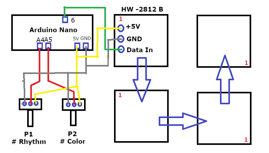
Circuit
Circuit
Comments
Only logged in users can leave comments
TheTNR
0 Followers
•0 Projects
Table of contents
Intro
2
0