Lapsed Time Timer
This is used as a clock accuracy check by triggering the minute or hour hands.
Components and supplies
Arduino UNO
OPB625 Slotted Optical Switch
Linksprite 16x2 LCD Shield
Tools and machines
Soldering iron (generic)
Code
Lapsed Time Timer
arduino
Reads an input on Trigger Pin. This starts the lapsed // time timer. On the going low of Trigger Pin the lapsed // time is logged. The minimum time that can be measured // is 1 minute as the trigger is inhibited for this time.
1//************************************************************
2//                     Lapsed   Time Timer                    //
3//                By Robert Leney  January 2017              //
4//************************************************************
5//
6//     Reads an input on Trigger Pin. This starts the lapsed
7//    time timer. On   the going low of Trigger Pin the lapsed
8//    time is logged. The minimum time   that can be measured
9//    is 1 minute as the trigger is inhibited for this   time.
10//
11//***********************************************************
12//
13//    Uses 16x2 LCD display. LCD pins need changing to suit
14//    your   setup.
15//
16//***********************************************************
17#include   <stdio.h>
18#include <LiquidCrystal.h>
19
20// LCD Initalisation ...............................
21LiquidCrystal   lcd(8, 13, 9, 4, 5, 6, 7);
22//..................................................
23
24//Array   Constants
25enum Mode { Days, Hrs, Mins, Secs};
26
27
28// Time constant
29const   int second = 1000;
30
31// Assign Trigger input pin
32const int Trigger = 3;
33
34
35void   setup() {
36// Setup LCD Display .........................
37
38  lcd.begin(16,   2);
39  lcd.clear();
40  lcd.setCursor(0,0);
41//...........................................
42
43//   Initalise input
44pinMode( Trigger, INPUT);
45}
46
47void loop() {
48// Timer   ...............................................
49  bool Tripped = false;
50
51  // Initalised here to expand scope
52       int secs  = 0;
53       int   mins  = 0;
54       int hours = 0;
55       int days  = 0;
56  //...............................
57
58  Serial.println("STARTED ");
59  lcd.print("STARTED ");
60    for   (days=0; days < 7; ++days){
61       for (hours=0; hours < 23; ++hours){
62           for (mins=0; mins <59; ++mins){
63            for (secs=0; secs < 59;   ++secs){
64                  // Counting Output
65                  lcd.setCursor(0,1);
66                   lcd.print("H ");
67                  lcd.print(hours);
68                   lcd.print(":M ");
69                  lcd.print(mins);
70                  lcd.print(":S ");
71                  lcd.print(secs);
72                   lcd.print(" ");
73
74
75                   if(digitalRead(Trigger) == LOW && Tripped == false){
76                    Tripped   = true;   // Inhibit Log for 1 minute
77                      //Logged Output
78                       lcd.clear();
79                      lcd.setCursor(0,0);
80                       lcd.print("H ");
81                      lcd.print(hours);
82                      lcd.print(":M ");
83
84                       lcd.print(mins);
85                      lcd.print(":S   ");
86                      lcd.print(secs);
87                      days=0;
88                      hours=0;
89                      mins=0;
90                      secs=0;
91                   }
92                 delay(second);                    //delay   1 second
93           }
94           Tripped = false;
95        }
96
97     }
98  }
99  //End Timer ..............................................................
100}
Lapsed Time Timer
arduino
Reads an input on Trigger Pin. This starts the lapsed // time timer. On the going low of Trigger Pin the lapsed // time is logged. The minimum time that can be measured // is 1 minute as the trigger is inhibited for this time.
1//************************************************************
2//                     Lapsed  Time Timer                    //
3//                By Robert Leney  January 2017             //
4//************************************************************
5//
6//    Reads an input on Trigger Pin. This starts the lapsed
7//    time timer. On  the going low of Trigger Pin the lapsed
8//    time is logged. The minimum time  that can be measured
9//    is 1 minute as the trigger is inhibited for this  time.
10//
11//***********************************************************
12//
13//    Uses 16x2 LCD display. LCD pins need changing to suit
14//    your  setup.
15//
16//***********************************************************
17#include  <stdio.h>
18#include <LiquidCrystal.h>
19
20// LCD Initalisation ...............................
21LiquidCrystal  lcd(8, 13, 9, 4, 5, 6, 7);
22//..................................................
23
24//Array  Constants
25enum Mode { Days, Hrs, Mins, Secs};
26
27
28// Time constant
29const  int second = 1000;
30
31// Assign Trigger input pin
32const int Trigger = 3;
33
34
35void  setup() {
36// Setup LCD Display .........................
37
38  lcd.begin(16,  2);
39  lcd.clear();
40  lcd.setCursor(0,0);
41//...........................................
42
43//  Initalise input
44pinMode( Trigger, INPUT);
45}
46
47void loop() {
48// Timer  ...............................................
49  bool Tripped = false;
50
51  // Initalised here to expand scope
52       int secs  = 0;
53       int  mins  = 0;
54       int hours = 0;
55       int days  = 0;
56  //...............................
57
58  Serial.println("STARTED ");
59  lcd.print("STARTED ");
60    for  (days=0; days < 7; ++days){
61       for (hours=0; hours < 23; ++hours){
62          for (mins=0; mins <59; ++mins){
63            for (secs=0; secs < 59;  ++secs){
64                  // Counting Output
65                  lcd.setCursor(0,1);
66                  lcd.print("H ");
67                  lcd.print(hours);
68                  lcd.print(":M ");
69                  lcd.print(mins);
70                  lcd.print(":S ");
71                  lcd.print(secs);
72                  lcd.print(" ");
73
74
75                  if(digitalRead(Trigger) == LOW && Tripped == false){
76                    Tripped  = true;   // Inhibit Log for 1 minute
77                      //Logged Output
78                      lcd.clear();
79                      lcd.setCursor(0,0);
80                      lcd.print("H ");
81                      lcd.print(hours);
82                      lcd.print(":M ");
83
84                      lcd.print(mins);
85                      lcd.print(":S  ");
86                      lcd.print(secs);
87                      days=0;
88                      hours=0;
89                      mins=0;
90                      secs=0;
91                  }
92                 delay(second);                    //delay  1 second
93           }
94           Tripped = false;
95        }
96
97    }
98  }
99  //End Timer ..............................................................
100}
Downloadable files
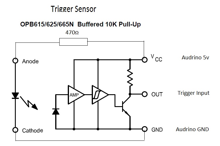
OPB625 Slotted Optical Switch wiring.
Connections and wiring for the optical sensor
OPB625 Slotted Optical Switch wiring.
Comments
Only logged in users can leave comments
bobbylegend
0 Followers
•0 Projects
Table of contents
Intro
1
0