Components and supplies
LEDs
Arduino UNO
Analog joystick (Generic)
Jumper wires (generic)
Male/Female Jumper Wires
Resistor 221 ohm
Project description
Code
WhackALED
arduino
Downloadable files
LED Whack-a-mole schematic
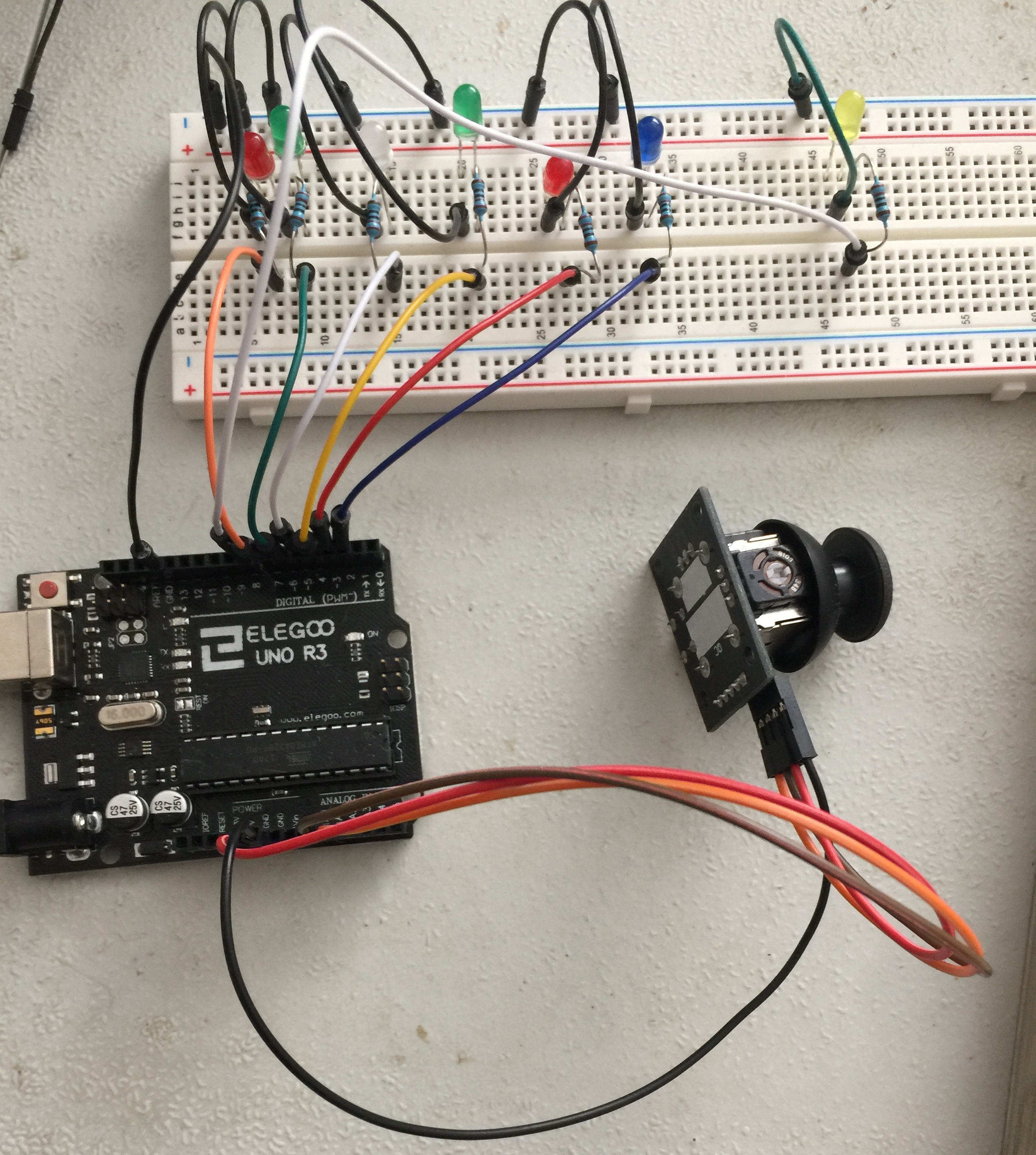
Everything should match the real picture of the project except for the joystick. My joystick has 5 pins, 4 or which I have used: named from top to bottom "GND", "+5V", "VRx", and "VRy". "GND" and "+5V" are connected to GND and 5V on the arduino, "VRx" and "VRy" are connected to A0 and A1.
LED Whack-a-mole schematic
Whack-a-mole LED
Everything should match the real picture of the project except for the joystick. My joystick has 5 pins, 4 or which I have used: named from top to bottom "GND", "+5V", "VRx", and "VRy". "GND" and "+5V" are connected to GND and 5V on the arduino, "VRx" and "VRy" are connected to A0 and A1.
Whack-a-mole LED

Real Picture
Real Picture
Whack-a-mole LED
Everything should match the real picture of the project except for the joystick. My joystick has 5 pins, 4 or which I have used: named from top to bottom "GND", "+5V", "VRx", and "VRy". "GND" and "+5V" are connected to GND and 5V on the arduino, "VRx" and "VRy" are connected to A0 and A1.
Whack-a-mole LED
Real Picture
Real Picture
LED Whack-a-mole schematic
Everything should match the real picture of the project except for the joystick. My joystick has 5 pins, 4 or which I have used: named from top to bottom "GND", "+5V", "VRx", and "VRy". "GND" and "+5V" are connected to GND and 5V on the arduino, "VRx" and "VRy" are connected to A0 and A1.
LED Whack-a-mole schematic
Comments
Only logged in users can leave comments
courtlandjensen
0 Followers
•0 Projects
Table of contents
Intro
36
0